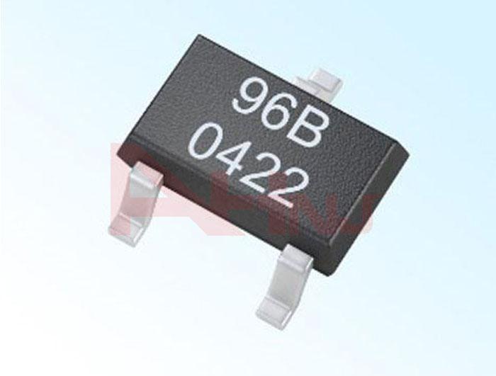
What are the Common Causes of Hall IC Failure?
In the process of using Hall IC, we often encounter the situation where Hall stops working after a period of time. At this time, the Hall chip may be damaged. What causes it? As a Latch Type Hall Sensor Factory, I tell you that you can analyze and detect from the following aspects:
1. First check the external circuit for any short circuit or open circuit caused by false soldering and missing soldering.
2. The Hall of the switch type generally requires an external pull-up resistor to work properly, check whether the resistance is normal.
3. Check the magnets separately. Some magnets are too long to demagnetize the magnets, resulting in Hall's insensitivity and malfunction.
4. Whether it exceeds the temperature range of the Hall itself. If the temperature is too high, the Hall will be damaged and the magnet will be demagnetized.
5. Check whether the voltage and current are stable and whether they are within the specified range of the Hall parameter. Partial upper limit or lower limit will cause the Hall to be unstable, and exceeding the parameter range will cause the Hall to be punctured and cause damage.
Linear Hall Sensor
Precautions when using Hall elements:
1. Hall is a sensitive device. Take precautionary measures against static electricity during use and storage.
2. Appropriate power supply voltage, load circuit, and operating temperature are prerequisites for the normal operation of the Hall device. The supply voltage, load current, and operating temperature of the Hall device must not exceed the ranges specified in the specification.
3. The tools used, especially the soldering iron, must be strictly connected to the ground wire to ensure that the soldering iron does not leak electricity, that is, the iron sheet of the soldering iron is grounded. It is best to use a low-voltage thermostat adjustable soldering iron for welding.
4. All equipment should be strictly grounded, and no leakage should be confirmed one by one with an electric pen before starting work.
5. It is required that the printed circuit board and Hall device pins be strictly cleaned so that it has good wettability with solder.
6. Because the mechanical stress will cause the magnetic sensitivity of the Hall device to drift, the mechanical force applied to the device case and the lead should be minimized during installation. If the pin needs to be bent, please operate 3mm away from the root of the lead.
7. Solder the wires in parallel to the pins of the Hall device. Do not move the pins of the Hall device during welding.
8. Recommended soldering temperature: soldering iron, the recommended temperature is 350 ℃, the longest 5 seconds; wave soldering: the recommended maximum temperature is 260 ℃, the longest 3 seconds; infrared reflow soldering: the recommended maximum 245 ℃, the longest 10 seconds.
9. There must be no burrs on the solder joints to avoid puncturing the heat shrinkable tube and causing the short circuit to burn out the Hall device.
10. The heat-shrinkable tube must be placed on the root of the Hall device to ensure that the device is fully insulated. It is best to lay a layer of insulating paper under the heat-shrinkable tube and the lead.
Our company also sells Linear Hall Sensor, welcome to consult.

评论
发表评论